What Are CDP and LLDP?
CDP (Cisco Discovery Protocol):
A proprietary Layer 2 protocol developed by Cisco.
Purpose: Discover and share information about directly connected Cisco devices. It’s enabled by default on Cisco devices.
Shares: Device IDs, IP addresses, interface info, and capabilities.
Only works between Cisco devices.
LLDP (Link Layer Discovery Protocol):
IEEE 802.1AB standard (vendor-neutral).
Purpose: Discover and advertise connected device info on the local network segment.
Works across most vendors (Cisco, Juniper, Huawei, etc.).
Shares similar details to CDP: system name, interface, platform, capabilities.
Essential for multi-vendor environments.
Why Use CDP/LLDP?
To map physical network topology quickly.
To document port connections.
For troubleshooting and effective Layer 2 management.
For building complex, multi-vendor networks.
Small Network Topology Example
Simple Topology:
Switch1: Cisco
Switch2: Juniper
Router: Huawei
Ports:
Switch1 (G0/1) ⇄ Switch2 (G0/1)
Switch1 (G0/2) ⇄ Router (G0/0)
The above topology allows you to demonstrate CDP (between Cisco devices) and LLDP (between Cisco, Juniper, and Huawei).
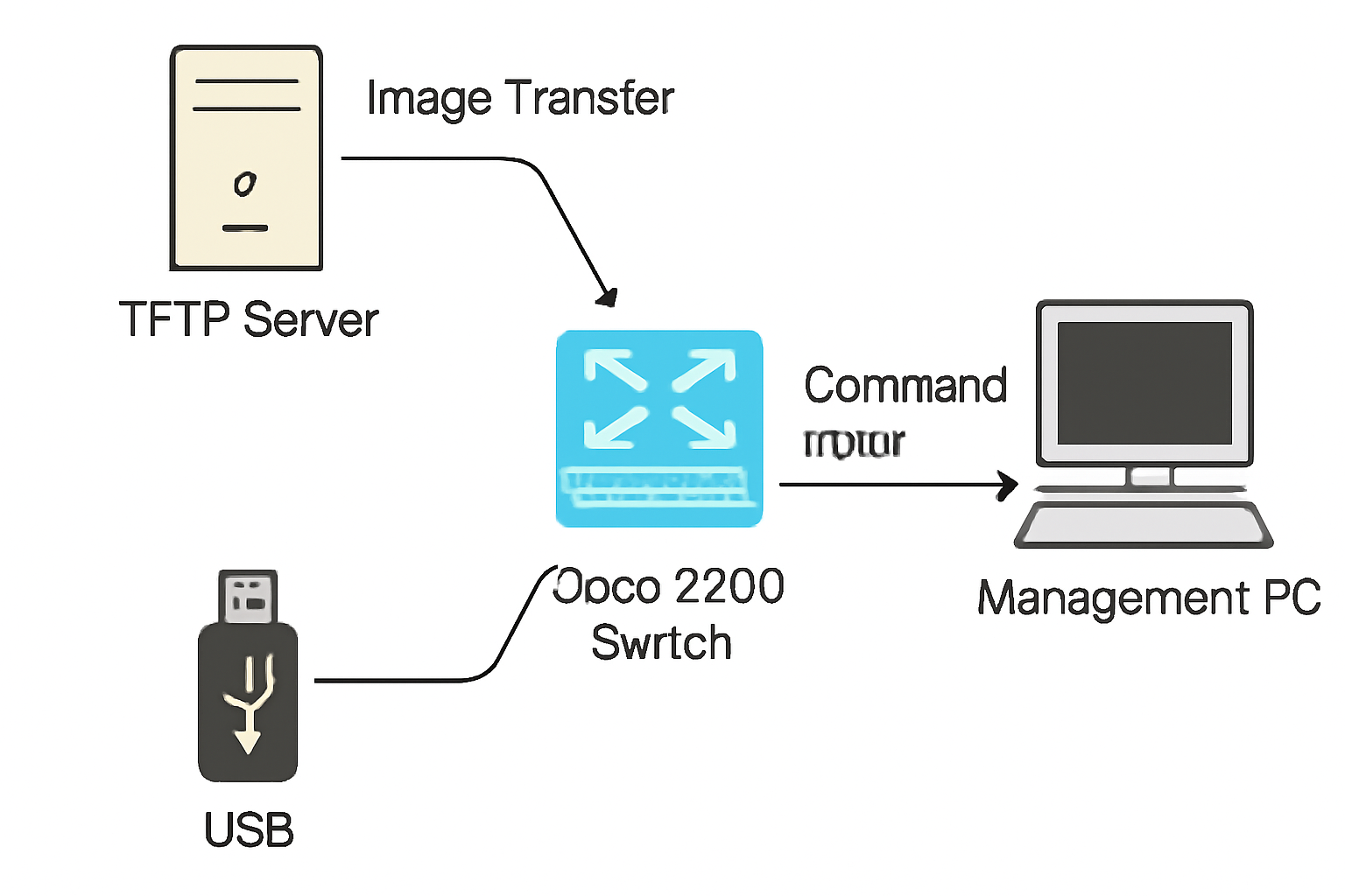
Lab Diagram (Reference)
Network topology diagrams typically show direct links between switches and routers. Each device’s interface can be labeled for clarity (e.g., Switch1 G0/1 → Switch2 G0/1).
Port Connectivity Table
| Device | Local Interface | Connected Device | Remote Interface |
|---|
| Switch1 | G0/1 | Switch2 | G0/1 |
| Switch1 | G0/2 | Router | G0/0 |
| Switch2 | G0/1 | Switch1 | G0/1 |
| Router | G0/0 | Switch1 | G0/2 |
Configuration: CDP and LLDP
1. Cisco Switch (CDP and LLDP)
Enable CDP Globally: (usually on by default)
Enable CDP on an Interface:
Enable LLDP Globally:
Enable LLDP on an Interface:
Verify:
2. Juniper Switch (LLDP Only)
Enable LLDP Globally:
To enable on one interface:
Verify:
3. Huawei Switch (LLDP Only)
Enable LLDP Globally:
Configure Transmission Interval, Delay, Hold:
Verify:
Best Practices and Lab Demo
Use discovery protocols only on network-facing interfaces, never outward-facing ones (e.g., internet-facing ports) for security.
Always document port connectivity for future troubleshooting.
In lab environments, use Packet Tracer or eNSP to visualize device neighbor tables and network topology as discovered by CDP/LLDP.
After enabling protocols, use “show” commands to validate topology discovery and document real port connectivity.
By following these steps, you get both vendor-specific and vendor-neutral topology discovery, accurate documentation, and robust troubleshooting capability for modern networks.
To illustrate the CDP and LLDP protocols and their discovery capabilities in a small lab, here’s a sample topology diagram—with practical descriptions, port connectivity, and best-practice labeling.
Sample CDP/LLDP Lab Topology and Port Map
Simple Network Topology Diagram
Below is a typical small lab setup (text version for clarity):
Connections:
Router (Huawei, G0/0) ⇄ Switch1 (Cisco, G0/2)
Switch1 (Cisco, G0/1) ⇄ Switch2 (Juniper, G0/1)
This diagram can be easily recreated in tools like Cisco Packet Tracer, Huawei eNSP, or GNS3.
Port Connectivity Table
| Device | Local Interface | Connected Device | Remote Interface |
|---|
| Huawei Router | G0/0 | Cisco Switch1 | G0/2 |
| Cisco Switch1 | G0/2 | Huawei Router | G0/0 |
| Cisco Switch1 | G0/1 | Juniper Switch2 | G0/1 |
| Juniper Switch2 | G0/1 | Cisco Switch1 | G0/1 |
Lab Notes
CDP will function between Cisco devices. In this topology, that means only Cisco Switch1 would show CDP neighbors if directly connected to another Cisco device.
LLDP will function between all devices due to its vendor-neutral standard. In this setup, Juniper, Huawei, and Cisco can discover each other via LLDP as long as it’s enabled on connecting ports.
These diagrams and port maps are helpful for quick troubleshooting, validating cabling, and confirming neighbor discovery outputs.
Best Practices for Using Lab Topologies
Clearly label all physical and logical interfaces in diagrams.
Map uplinks/downlinks with accurate port names (i.e., G0/1, G0/2).
Use “show cdp neighbors” on Cisco, “show lldp neighbors” on Cisco/Juniper/Huawei to validate live topology.
Save or screenshot your topology views in your simulation tool for documentation.


